
Windows and sight glass
Plane-parallel plates for UV, visible, and IR transmission, sensor protection, debris shielding, and environmental separation between a process and the optics watching it.
From .100″ to 16″ high and .008″ to 4″ thick
IRD manufactures precision flat optics for OEMs in the medical, laser, defense, aerospace, security, sensing, and process control industries. Working from customer drawings, IRD manufactures flat optical components for applications requiring demanding flatness, surface quality, dimensional precision, and long-term reliability.
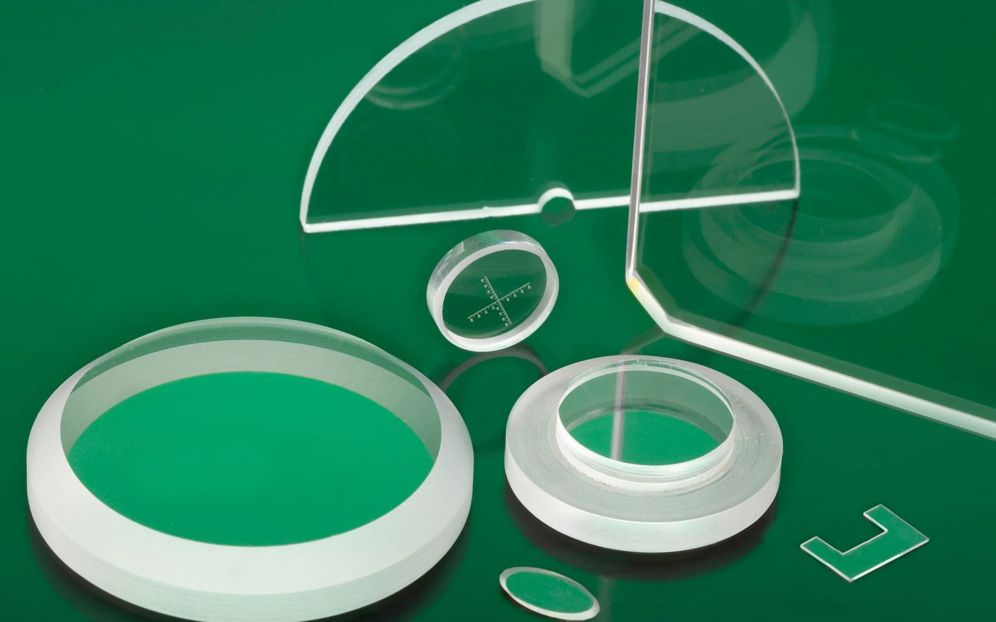
IRD flat optics are used in imaging systems, laser platforms, aerospace instrumentation, medical devices, sensing technologies, and advanced industrial equipment where optical precision and repeatable performance are critical. When optical performance depends on precision manufacturing, advanced materials, and tight tolerances, IRD delivers flat optics manufactured to the customer drawing.
Plane-parallel plates for UV, visible, and IR transmission, sensor protection, debris shielding, and environmental separation between a process and the optics watching it.
From .100″ to 16″ high and .008″ to 4″ thick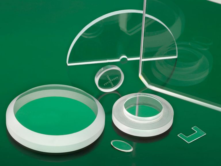
First- and second-surface flat and laser mirrors for interferometry, beam steering, folding, and imaging, from protected aluminum through high-laser-damage-threshold stacks, certified to whatever data the program requires.
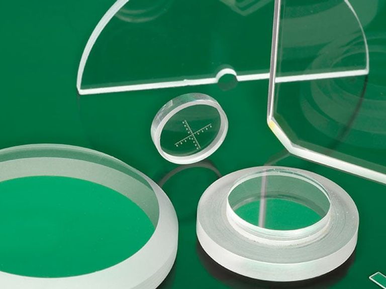
Filter glass from Schott, Kopp, Ohara, Hoya, and others, plus in-house thin-film coatings from UV through IR, for transmission, blocking, and wavelength-control requirements.
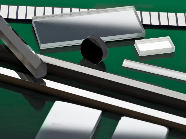
Chrome, precious-metal, and aluminum patterns for filters, masks, reference gauges, and datums, and precision reticles for semiconductor, inspection, and medical systems.
Details down to sub-micron line widthsThese are IRD's published capability limits across materials and geometries, not a grade every part ships to. Open the process that controls your critical surface and quote against that one.
Precision machining, grinding, and optical polishing, thin-film optical coatings and strengthening processes, and precision fabrication of glass, sapphire, fused silica, and ceramic materials, from prototype through full production.
| Attribute | Typical | Best case |
|---|---|---|
| Surface flatnessWindows, mirrors, and reference flats | 1 wave | < 1/20 wave |
| ParallelismBest-case polishing parallelism is < 2 arc sec; see the Polishing tab | < 15 arc sec | .00003″ over 9″+ substrates |
| Surface roughnessPolished optical faces | Ra < 1 µin | Ra < 2 Å |
| Dimensional toleranceTight dimensional and edge quality tolerances | ±.005″ | ±.0005″ |
Flatness and parallelism are separate controls, and both are lost more often to fixturing and handling than to the polish itself. These are the controls IRD holds across a production run.
Double-side lapping machines both faces at once between a floating upper plate and a lower plate, doubling throughput and, more importantly, avoiding the clamping stress that single-side work introduces. IRD's published lapping capability runs to ±.000010 inch on flatness and parallelism.
Pitch plates hold a semi-fluid surface, grooved by hand or machine so the polishing slurry can reach the whole component. The method both reaches Ra under 5 Å and minimizes the surface deformation at the edge roll that makes an otherwise flat part unusable near its aperture edge.
Pitch polishing covers components from 20 mm to 600 mm in diameterThe inspection floor includes Zygo GPI, NewView, and Verifire XPZ systems; Nikon 6D interferometry; TriOptics Triangle and PrismMaster; Starrett MVR300; Zeiss Spectrum and O-Inspect; Micro-Vu automated vision; and Tagarno digital microscopy. A flatness number without a stated measurement condition is a claim, not a specification.
Masking, fixture contact, edge handling, and witness sampling for a patterned or coated flat all depend on decisions made before the surface exists. Deciding them afterwards is how a good polish becomes a rejected coating run.
IRD manufactures precision flat optics and coated optical components for OEMs in the medical, laser, aerospace, defense, sensing, and advanced industrial markets. We help customers select the optimal substrate materials, fabrication processes, and coating technologies based on optical performance requirements, environmental conditions, thermal stability, and long-term durability. IRD manufactures flat optics and coordinates coating processes to meet customer requirements for dimensional stability, optical clarity, transmission efficiency, and environmental durability. Our materials and coatings are used in imaging systems, laser platforms, aerospace instrumentation, medical devices, sensing technologies, and process control applications where precision optical performance is critical. When optical performance depends on precision fabrication, advanced materials, and coating expertise working together, IRD delivers flat optics manufactured to the customer drawing.
The answers an applications engineer would give you on the first call.
Start a quoteIRD reports regularly achieving 1/10 wave or better on flat optics, against a best-case polishing capability of better than 1/20 wave. Neither published figure states a reference wavelength, send your measurement condition and the team will confirm against it rather than against a datasheet.
The published window range runs .100″ to 16″ high in thicknesses from .008″ to 4″, across N-BK7, B270, borosilicate, fused silica, fused quartz, high-index glass, sapphire, silicon, and other IR materials. Parallelism of .00003″ is published across a 9″-or-larger substrate, and flat optics are held to better than 15 arc seconds; the best-case polishing capability is better than 2 arc seconds.
IRD's quoting checklist: application, product type, volume potential and schedule, material, dimensions, surface quality, coatings, assembly, cleaning, and packaging. Attach the drawing. For a new design the technical team runs a no-cost Design for Manufacturability review before quoting, then estimates prototype and production volumes separately.
No. IRD manufactures to your print or performance requirement and contributes material, process, and manufacturability input, the design stays with your team. When a print calls for tighter tolerances than the application requires, IRD will flag the potential over-specification, since it can add unnecessary cost. Final optical design decisions remain yours.
Machining runs to 30″ × 16″ × 16″, polishing to 36″ diameter, grinding to 24″ diameter at 6″ height, lapping to 13.3″ diameter, waterjet to 40″ × 24″ × 2″, and dicing to 8″ diameter at .300″ thick. Larger geometry is quoted against whichever process controls the critical surface.
IRD applies basic anti-reflective and metallic coatings in-house for quick turnaround. Other coating requirements are handled through select, vetted coating partners. Name the coating target in the RFQ and the team will confirm the route before quoting.
IRD is registered with the Directorate of Defense Trade Controls, and controlled programs are manufactured and stored domestically across the Litchfield and Alexandria, Minnesota facilities. Both plants operate under quality systems certified to ISO 9001:2015 and ISO 13485:2016 for ultra-high-precision glass, optical, and ceramic components.
Packaging is tailored to the part and can include multi-layer foam, custom corrugated packaging, gel packs for sensitive optics, and military-grade cases. Components are supported on edges or non-critical surfaces outside the clear aperture and held against shifting in transit.
Use these IRD references when reviewing precision flat optics requirements.
The mirror families IRD manufactures for beam steering, folding, interferometry, imaging, and high-power industrial laser systems, and the sole-source relationships behind them.
ArticleTechnical articleHow long-pass, short-pass, bandpass, notch, and dichroic filters differ, and when filter glass, a thin-film coating, or a combination of both is the right route.
ArticleTechnical articleHow MIL-PRF-13830B scratch and dig numbers are assigned and counted, where ISO 10110 differs, and why over-specifying surface quality moves cost without moving function.
Article
Send the drawing with the aperture and thickness, the flatness and parallelism requirements and the wavelength and method they are measured at, scratch-dig per face, substrate, any pattern or coating, mounting condition, annual volume, and schedule. For a new design, the technical team runs a no-cost Design for Manufacturability review before quoting.
Final capability is quoted to the drawing. Achievable tolerance depends on material, feature size, geometry, coating, and production volume. Or call 320.693.7217. If you are qualifying a second source for a flat already in production, say so, IRD asks for that work directly.