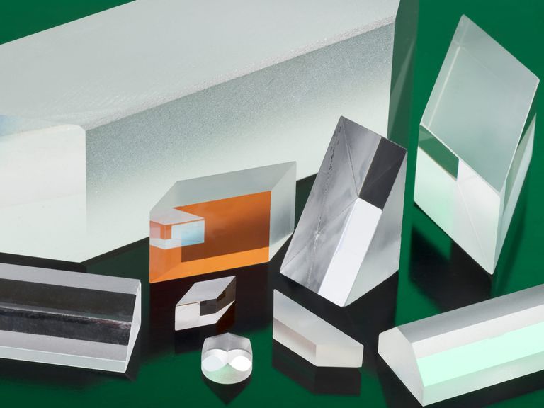
Right angle and roof
Right-angle prisms turn a beam 90 degrees or retroreflect it through two reflections. Roof prisms fold the same path while inverting the image along one axis in a more compact envelope.

IRD manufactures custom optical prisms for OEM applications in laser systems, imaging technologies, aerospace instrumentation, medical devices, sensing systems, and advanced photonics. Working from customer drawings, IRD fabricates prisms for beam steering, image rotation, light displacement, alignment correction, and optical path control.
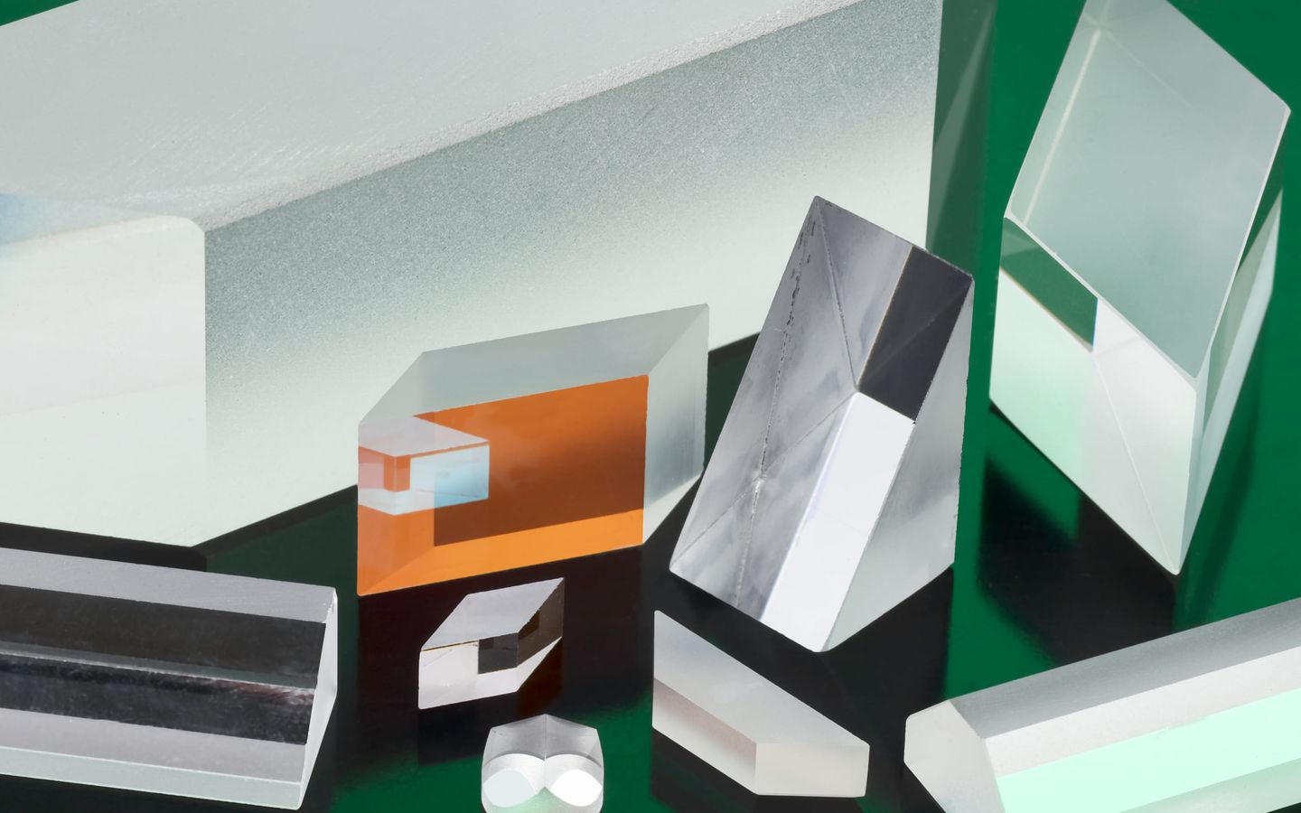
IRD prisms are used in laser beam steering systems, imaging platforms, aerospace instrumentation, medical devices, spectroscopy systems, semiconductor equipment, and advanced sensing technologies where precision optical control is critical. When optical systems require precise beam manipulation, dimensional stability, and repeatable performance, IRD delivers optical prisms manufactured to the customer drawing.
Right-angle prisms turn a beam 90 degrees or retroreflect it through two reflections. Roof prisms fold the same path while inverting the image along one axis in a more compact envelope.
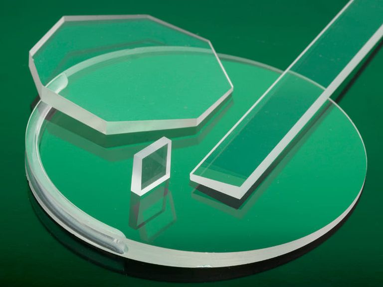
Penta prisms hold a fixed 90-degree deviation without inverting the image, even under small mounting movement. Dove prisms rotate or invert an image as the prism turns about its long axis.
Coated pentas are also used as beamsplitters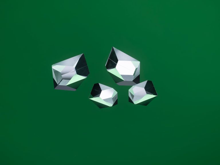
Wedges deviate a beam at a controlled shallow angle, and two together steer it. Rhomboids displace a beam laterally without changing its direction or inverting the image.
NIST-traceable wedge certification accurate to within 5 arc seconds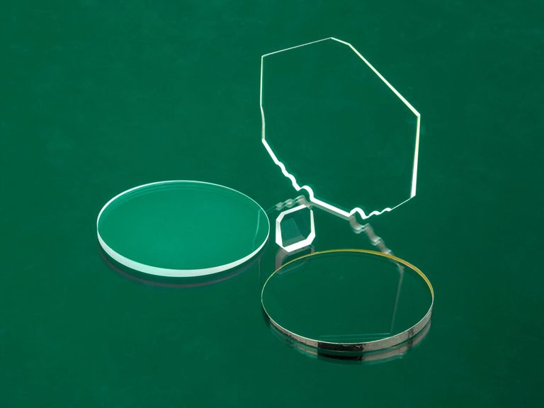
Challenging variations, custom prism geometries and optical assemblies, and entirely new prism forms developed for applications that no standard geometry covers.
These are IRD's published capability limits across materials and geometries, not a grade every part ships to. Open the process that controls your critical surface and quote against that one.
Precision grinding and polishing for high optical clarity, with UV, visible, and IR wavelength optimization, from prototype through production manufacturing. Specify each attribute to what the assembly needs.
| Attribute | Typical | Best case |
|---|---|---|
| Angle toleranceBeam steering and interferometric alignment | 5 arc min | 3 arc sec |
| Surface flatnessWavefront-critical faces | 1 wave | < 1/20 wave |
| Surface roughnessPolished prism faces | Ra < 1 µin | Ra < 2 Å |
| ParallelismRhomboids, wedges, and reference faces | 30 arc sec | < 2 arc sec |
| Dimensional toleranceMounting features and interfaces | ±.005″ | ±.0001″ |
An arc second is roughly a millimeter seen from two hundred meters away. Nothing about that survives a process that was designed for dimensions and then asked to hold angles. These are the controls IRD holds across a production run.
IRD's inspection floor runs a Nikon autocollimator alongside toolmaker's scopes and interferometers. Blocking sets the angle; autocollimation is what proves it held after polishing, and it is where a drifting fixture shows up before the batch finishes.
IRD inspects to MIL-PRF-13830B and ISO 10110. The dig number is measurable, the diameter of the largest surface dig in hundredths of a millimeter, but the scratch number is a visual brightness comparison and varies with the inspector. Naming the standard on the print is what makes the acceptance repeatable.
Over-specifying scratch-dig raises cost without changing function on most facesIRD certifies custom optical wedges, from precision NIST-certifiable references through custom lighting wedges, accurate to within 5 arc seconds for the optical angle or angle of deviation.
Coatings are applied to prism faces and to the circumference, and IRD works in solder-compatible as well as dielectric and metallic stacks. Deciding that before polishing is what determines masking, fixture contact, and edge handling.
IRD optical prisms are available in a wide range of advanced optical materials, including fused silica, BK-7, sapphire, infrared transmitting materials, and specialty optical substrates engineered to application requirements.
The answers an applications engineer would give you on the first call.
Start a quote3 arc seconds is IRD's published best-case polishing angle capability; typical is 5 arc minutes. Which faces earn the tighter number is a per-print decision, because each one costs process time. Name the angles that drive system performance and let the rest run at typical.
Name the standard on the print. IRD inspects to MIL-PRF-13830B and ISO 10110, the dig number is measurable, but the scratch number is a visual brightness comparison that varies with the inspector, so the standard is what makes acceptance repeatable. Over-specifying scratch-dig raises cost without changing function on most faces.
IRD's quoting checklist: application, product type, volume potential and schedule, material, dimensions, surface quality, coatings, assembly, cleaning, and packaging. Attach the drawing. For a new design the technical team runs a no-cost Design for Manufacturability review before quoting, then estimates prototype and production volumes separately.
No. IRD manufactures to your print or performance requirement and contributes material, process, and manufacturability input, the design stays with your team. When a print calls for tighter tolerances than the application requires, IRD will flag the potential over-specification, since it can add unnecessary cost. Final optical design decisions remain yours.
Machining runs to 30″ × 16″ × 16″, polishing to 36″ diameter, grinding to 24″ diameter at 6″ height, lapping to 13.3″ diameter, waterjet to 40″ × 24″ × 2″, and dicing to 8″ diameter at .300″ thick. Larger geometry is quoted against whichever process controls the critical surface.
IRD applies basic anti-reflective and metallic coatings in-house for quick turnaround. Other coating requirements are handled through select, vetted coating partners. Name the coating target in the RFQ and the team will confirm the route before quoting.
IRD is registered with the Directorate of Defense Trade Controls, and controlled programs are manufactured and stored domestically across the Litchfield and Alexandria, Minnesota facilities. Both plants operate under quality systems certified to ISO 9001:2015 and ISO 13485:2016 for ultra-high-precision glass, optical, and ceramic components.
Packaging is tailored to the part and can include multi-layer foam, custom corrugated packaging, gel packs for sensitive optics, and military-grade cases. Components are supported on edges or non-critical surfaces outside the clear aperture and held against shifting in transit.
Use these IRD references when reviewing precision optical prisms requirements.
How MIL-PRF-13830B scratch and dig numbers are assigned and counted, where ISO 10110 differs, and why over-specifying surface quality moves cost without moving function.
ArticleTechnical articleThe instruments behind an acceptance number, optical profilers, the two classes of white-light interferometer, and what each one measures on a finished surface.
ArticleWebinarIRD's applications team on the information that makes a quote accurate the first time, and the omissions that cause a requote.
Recording
Send the drawing with the deviation or image orientation the assembly needs, the controlling angles and their tolerances, surface figure and scratch-dig per face, coated faces including the circumference, material, annual volume, and the inspection standard you will accept against. For a new design, the technical team runs a no-cost Design for Manufacturability review before quoting.
Final capability is quoted to the drawing. Achievable tolerance depends on material, feature size, geometry, coating, and production volume. Or call 320.693.7217. If you need a NIST-traceable wedge certificate with the part, say so at the RFQ, it changes the inspection route.