
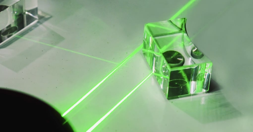
Cylindrical optical components solve beam-shaping and imaging problems that conventional round optics do not address in the same way. Rather than focusing light equally in every direction, they apply optical power along one axis. That behavior can create a line focus, change a beam’s width in one direction, or correct directional distortion within an optical system. A complete look at different cylindrical lenses begins with understanding how each form controls light and affects the finished assembly.
Understand How Cylindrical Optics Change Light
A cylindrical optical surface curves in one direction while remaining flat along the perpendicular direction. Because of that geometry, the component changes light along one axis and leaves the other axis largely unchanged. A positive cylinder brings light toward a line focus, while a negative cylinder spreads light along the powered direction.
This one-axis behavior allows a designer to adjust beam width or correct a directional focusing error without changing both dimensions equally.
Orientation matters just as much as optical power. Rotating the part changes the direction in which it acts, so the cylinder axis must align with the intended beam dimension. A component with the correct focal properties can still produce the wrong result when its powered axis is mounted incorrectly.
Compare Positive and Negative Cylindrical Forms
Positive cylindrical lenses converge light along the powered axis. They are often used when a system needs to narrow a beam in one direction or create a focused line. The perpendicular axis remains comparatively unchanged, producing a line rather than a point focus.
Negative cylindrical forms perform the opposite function. They diverge light along one axis and can expand a beam before it reaches another optical element or working plane. This approach may help when the source is too narrow in one direction.
The correct sign of optical power depends on the starting condition and intended output. Designers should consider the incoming beam shape first, then account for working distance and component spacing.
Common forms include:
- Plano-convex cylinders, which use one flat surface and one outward-curved surface to converge light
- Plano-concave cylinders, which use one flat surface and one inward-curved surface to spread light
- Double-convex cylinders, which use two outward-curved surfaces to provide positive cylindrical power
- Double-concave cylinders, which use two inward-curved surfaces to provide negative cylindrical power
Match Each Form to the Optical Layout
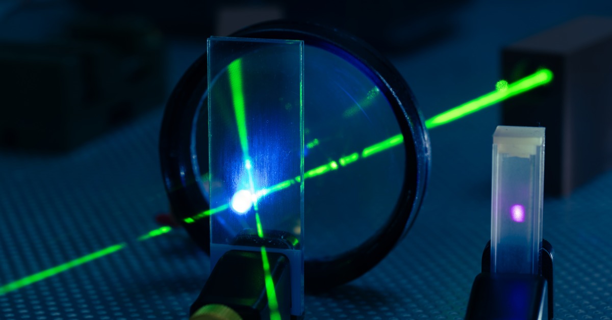
Plano-convex components are often considered for line generation and one-axis beam compression. Their geometry can suit layouts that need positive cylindrical power with one flat mounting or reference surface. The direction of the curved face relative to the incoming beam may influence performance, so evaluate that detail within the full design.
Plano-concave components are commonly used for one-axis expansion. They can widen a narrow beam before it reaches a detector, aperture, or another beam-shaping element. Their effectiveness depends on both their focal properties and their position within the optical path.
Double-convex and double-concave components may be useful when the system favors two curved surfaces. They are not automatically more precise or effective than plano forms. The right choice depends on the optical layout and packaging limits.
Different cylindrical lenses may support applications such as:
- Producing a line of light for inspection or scanning
- Reshaping an elliptical laser beam before another optical stage
- Correcting one-axis focus differences in an imaging or sensing system
- Expanding or compressing a beam to fit a detector or aperture
The selection process should connect the form to the larger assembly. Buyers need a clear picture of the incoming light and required output so a manufacturer can evaluate the geometry and material effectively.
Specify the Features That Affect Manufacturability
Material selection affects transmission, thermal behavior, durability, and coating compatibility. Optical glass may fit many visible-light systems, while fused silica or another technical material may be more appropriate for a different wavelength range or operating environment. The choice should reflect the application rather than a general substrate preference.
The drawing should clearly communicate the powered axis and the geometry that establishes it. It should also identify the dimensions and optical requirements that affect function. Missing details can force quoting and process planning to rely on assumptions.
Important specifications may include:
- Radius or focal requirements along the powered axis
- Clear aperture and edge dimensions
- Center thickness, wedge, and parallelism
- Surface quality and surface roughness
- Coating requirements and coated surfaces
- Axis orientation, marking, and mounting references
- Inspection wavelength and acceptance criteria
These requirements interact with one another. Tighter dimensional control may affect grinding and polishing, while stricter surface requirements may change handling and inspection needs. An early manufacturability review can help separate specifications that protect performance from those that add complexity without a clear benefit.
Plan for Alignment and Coating Requirements
Alignment deserves special attention because cylindrical power acts in one direction. A small rotational error can shift the controlled axis away from its intended orientation. Drawings may need a clear axis callout or marking requirement so the part can be installed consistently.
Mounting decisions should support the same alignment strategy. The component must be held without introducing stress, and the assembly may need a practical way to verify rotation during setup.
Optical coatings can reduce reflection or support transmission across a defined wavelength range. The coating choice should account for the substrate and operating wavelength. Depending on the application, the angle of incidence and energy level may also matter.
Coating requirements should identify which surfaces receive the coating and how performance will be evaluated. That clarity is especially useful when one surface is curved, and the other serves as a mechanical reference.
Define the Inspection and Quoting Package
Inspections should confirm the characteristics that matter to the optical system. Depending on the part, that may include dimensional checks, surface inspection, focal testing, or orientation verifications. The method should suit the requirement rather than appear on the drawing only because it was used for a previous part.
The inspection wavelength should be stated when optical performance changes with wavelength. Acceptance criteria should also be measurable and connected to the part’s function. Clear requirements help engineering, quality, and procurement teams work from the same definition of an acceptable component.
A useful quoting package may include:
- A controlled drawing or model
- The preferred material or required transmission range
- Coating and surface requirements
- Inspection criteria and documentation needs
- Prototype and expected production quantities
- Known assembly or mounting constraints
Buyers do not always need every optical term finalized before contacting a manufacturer. A technical discussion can help identify open decisions and translate a performance need into a measurable component requirement.
Select a Cylindrical Component With the Full System in Mind
Cylindrical components can focus, spread, or reshape light along one axis, but their form alone does not determine success. Material choice, axis orientation, coatings, mounting, and inspections all influence how the part performs after assembly. Reviewing those factors together can reduce ambiguity before a prototype or production order moves forward.
IRD Glass supports custom optical components for technical applications where standard parts may not fit the requirement. Share your print, beam-shaping goal, material needs, and inspection expectations to discuss manufacturability and request a quote for a build-to-spec cylindrical component.